Wire the Kisi Controller Pro 2
Since the Controller is the heart of the Kisi access control system, it's crucial to wire it properly. Please take a careful look at the below recommendations, then look up your lock/power setup, and follow the instructions.
Before proceeding, please check the white sticker located on the relays to confirm the controller model.
Required connections
- Low Voltage Wires (18-2 gauge)
- Ethernet (CAT5/CAT6 recommended)
- Power (60W 24V Universal Power Supply included)
Recommendations:
- Do not exceed 125 feet (38.1 meters) for your low voltage wiring (18-2 gauge wire) runs
- Do not exceed 300 feet (91.4 meters) for your ethernet (CAT5/CAT6) runs
Wiring instructions
Watch the video guide for an example of wiring a Kisi Controller Pro 2 to a fail-secure 24V lock with a wet contact and an REx device.
Do not wire anything to the controller while it's powered. Disconnect power before making any wiring changes.
The Kisi Controller Pro 2 can be wired with different types of locks, contact, and power used. Depending on your setup, the wiring might differ a bit. Find your setup and follow the instructions:
Fail-safe electric strikes, while rare, are wired the same way as magnetic locks. If you have a fail-safe electric strike, follow the magnetic lock instructions.
- Standalone fail-secure electric strike with wet contact
- Standalone fail-safe magnetic lock with wet contact
- External power supply & fail-secure electric lock with dry contact
- External power supply & fail-safe magnetic lock with dry contact
- External power supply & fail-safe magnetic lock with REx and motion sensor with dry contact
1. Standalone fail-secure electric strike with wet contact
With a fail-secure electric lock, if the power is interrupted or fails, the door stays locked. If you are using a wet contact, it means that the power will be supplied by the same circuit where the contact is connected.
For this scenario, follow the illustration below.
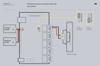
Wire the Kisi Controller Pro 2 to the electric strike
- Select one of the controller's four door relays. Note: The fifth (AUX) relay is for wiring intrusion detection hardware, such as sirens or third-party alarm systems.
- Identify the GND (Ground), NO (Normally Open), COM (Common), and NC (Normally Closed) pins
- Wire the GND (Ground) pin of the controller to the negative (-) wire of the strike
- Wire the NO (Normally Open) pin of the controller to the positive (+) wire of the strike
- On the controller, set the jumper into the correct wet position: 12VDC or 24VDC. Example: If you have two electric strikes that draw 12 volts / 2 amperes from the Kisi Controller Pro 2, you cannot power any more locks from the circuit board. You can still wire another two door locks to the Kisi Controller Pro 2, but only from their own separate power supply and as dry contacts.
- Verify that all connections are secure and there are no loose wires
Wiring a contact sensor
- Identify the general inputs on the left side of the controller. Note: two IN (Input) pins share one GND (Ground): IN1, GND, IN2, GND, IN3, etc.
- Wire the GND (Ground) pin of the controller to the negative wire of the contact sensor
- Wire the IN (Input) pin of the controller to the positive wire of the contact sensor
- Verify that all connections are secure and there are no loose wires
Wiring a REx (request-to-exit) device
- Identify the general inputs on the left side of the controller. Note: two IN (Input) pins share one GND (Ground): IN1, GND, IN2, GND, IN3, etc.
- Wire the GND (Ground) pin of the controller to the negative wire of the request-to-exit
- Wire the IN (Input) pin of the controller to the positive wire of the request-to-exit
- Verify that all connections are secure and there are no loose wires
Finalize the wiring
- Power the controller using the provided power supply and input. A blue light should come on if powered.
- Plug in the Ethernet cable. You should see a green blinking light on the top right-hand corner of the board. This indicates that the Kisi Controller Pro 2 is online.
The Kisi Controller Pro 2 does not support alternating current (AC) wiring, so make sure the lock can work on direct current (DC). Also, the Kisi Controller Pro 2 only supplies up to 4 amperes total for the door locks that are drawing power from the circuit board. If you wish to power up more doors, do not exceed a total of 4 amperes for each Kisi Controller Pro 2.
2. Standalone fail-safe magnetic lock with wet contact
Magnetic locks are an easy to install and quick to operate option. They only work as fail-safe as they require power to work. Fail-safe means that if the power is interrupted or fails, the door automatically unlocks.
For this scenario, follow the illustration below.

Wire the Kisi Controller Pro 2 to the magnetic lock
- Select one of the controller's four door relays. Note: The fifth (AUX) relay is for wiring intrusion detection hardware, such as sirens or third-party alarm systems.
- Identify the GND (Ground), NO (Normally Open), COM (Common), and NC (Normally Closed) pins
- Wire the GND (Ground) pin of the controller to the negative (-) wire of the magnetic lock
- Wire the NC (Normally Closed) pin of the controller to the positive (+) wire of the magnetic lock
- On the controller, set the jumper into the correct wet position: 12VDC or 24VDC. Example: If you have two electric strikes that draw 12 volts / 2 amperes from the Kisi Controller Pro 2, you cannot power any more locks from the circuit board. You can still wire another two door locks to the Kisi Controller Pro 2, but only from their own separate power supply and as dry contacts.
- Verify that all connections are secure and there are no loose wires
Wiring a contact sensor
- Identify the general inputs on the left side of the controller. Note: two IN (Input) pins share one GND (Ground): IN1, GND, IN2, GND, IN3, etc.
- Wire the GND (Ground) pin of the controller to the negative wire of the contact sensor
- Wire the IN (Input) pin of the controller to the positive wire of the contact sensor
- Verify that all connections are secure and there are no loose wires
Wiring a REx (request-to-exit) device
- Identify the general inputs on the left side of the controller. Note: two IN (Input) pins share one GND (Ground): IN1, GND, IN2, GND, IN3, etc.
- Wire the GND (Ground) pin of the controller to the negative wire of the request-to-exit
- Wire the IN (Input) pin of the controller to the positive wire of the request-to-exit
- Verify that all connections are secure and there are no loose wires
Finalize the wiring
- Power the controller using the provided power supply and input. A blue light should come on if powered.
- Plug in the Ethernet cable. You should see a green blinking light on the top right-hand corner of the board. This indicates that the Kisi Controller Pro 2 is online.
The Kisi Controller Pro 2 does not support alternating current (AC) wiring, so make sure the lock can work on direct current (DC). Also, the Kisi Controller Pro 2 only supplies up to 4 amperes total for the door locks that are drawing power from the circuit board. If you wish to power up more doors, do not exceed a total of 4 amperes for each Kisi Controller Pro 2.
3. External power supply & fail-secure electric lock with dry contact
When using a dry contact, an external power supply will be needed. For this scenario, follow the illustration below.
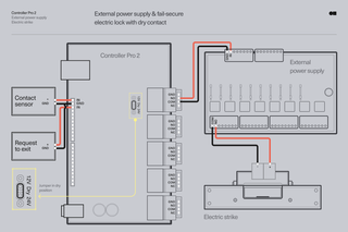
Wire the Kisi Controller Pro 2 to the external power supply
- Select one of the controller's four door relays. Note: The fifth (AUX) relay is for wiring intrusion detection hardware, such as sirens or third-party alarm systems.
- Identify the NO (Normally Open) and COM (Common) pins
- Wire the NO (Normally Open) pin of the controller to the IN (Input) wire of the external power supply
- Wire the COM (Common) pin of the controller to the GND (Ground) wire of the external power supply
- On the controller, set the jumper into the dry position
- Verify that all connections are secure and there are no loose wires
Wire the external power supply to the electric strike
- On the external power supply, identify the COM (Common) and NO (Normally Open) pins
- Wire the COM (Common) pin of the external power supply to the negative (-) wire of the electric strike
- Wire the NO (Normally Open) pin of the external power supply to the positive (+) wire of the electric strike
- Verify that all connections are secure and there are no loose wires
Wiring a contact sensor
- Identify the general inputs on the left side of the controller. Note: two IN (Input) pins share one GND (Ground): IN1, GND, IN2, GND, IN3, etc.
- Wire the GND (Ground) pin of the controller to the negative wire of the contact sensor
- Wire the IN (Input) pin of the controller to the positive wire of the contact sensor
- Verify that all connections are secure and there are no loose wires
Wiring a REx (request-to-exit) device
- Identify the general inputs on the left side of the controller. Note: two IN (Input) pins share one GND (Ground): IN1, GND, IN2, GND, IN3, etc.
- Wire the GND (Ground) pin of the controller to the negative wire of the request-to-exit
- Wire the IN (Input) pin of the controller to the positive wire of the request-to-exit
- Verify that all connections are secure and there are no loose wires
Finalize the wiring
- Power the controller using the provided power supply and input. A blue light should come on if powered.
- Plug in the Ethernet cable. You should see a green blinking light on the top right-hand corner of the board. This indicates that the Kisi Controller Pro 2 is online.
The Kisi Controller Pro 2 does not support alternating current (AC) wiring, so make sure the lock can work on direct current (DC). Also, the Kisi Controller Pro 2 only supplies up to 4 amperes total for the door locks that are drawing power from the circuit board. If you wish to power up more doors, do not exceed a total of 4 amperes for each Kisi Controller Pro 2.
4. External power supply & fail-safe magnetic lock with dry contact

Wire the Kisi Controller Pro 2 to the external power supply
- Select one of the controller's four door relays. Note: The fifth (AUX) relay is for wiring intrusion detection hardware, such as sirens or third-party alarm systems.
- On the relay, identify the COM (Common) and NO (Normally Open) pins
- Wire the COM (Common) pin of the controller to the GND (Ground) wire of the external power supply
- Wire the NO (Normally Open) pin of the controller to the IN (Input) wire of the external power supply
- On the controller, set the jumper into the dry position
- Verify that all connections are secure and there are no loose wires
Wire the magnetic lock to the external power supply
- Wire the negative (-) wire of the magnetic lock to the COM (Common) pin of the power supply
- Wire the positive (+) wire of the magnetic lock to the NC (Normally Closed) pin of the power supply
Wiring a contact sensor
- Identify the general inputs on the left side of the controller. Note: two IN (Input) pins share one GND (Ground): IN1, GND, IN2, GND, IN3, etc.
- Wire the GND (Ground) pin of the controller to the negative wire of the contact sensor
- Wire the IN (Input) pin of the controller to the positive wire of the contact sensor
- Verify that all connections are secure and there are no loose wires
Wiring a REx (request-to-exit) device
- Identify the general inputs on the left side of the controller. Note: two IN (Input) pins share one GND (Ground): IN1, GND, IN2, GND, IN3, etc.
- Wire the GND (Ground) pin of the controller to the negative wire of the request-to-exit
- Wire the IN (Input) pin of the controller to the positive wire of the request-to-exit
- Verify that all connections are secure and there are no loose wires
Finalize the wiring
- Power the controller using the provided power supply and input. A blue light should come on if powered.
- Plug in the Ethernet cable. You should see a green blinking light on the top right-hand corner of the board. This indicates that the Kisi Controller Pro 2 is online.
The Kisi Controller Pro 2 does not support alternating current (AC) wiring, so make sure the lock can work on direct current (DC). Also, the Kisi Controller Pro 2 only supplies up to 4 amperes total for the door locks that are drawing power from the circuit board. If you wish to power up more doors, do not exceed a total of 4 amperes for each Kisi Controller Pro 2.
5. External power supply & fail-safe magnetic lock with REx and motion sensor with dry contact
If you have the same setup as the previous, but you want to add a request to exit button and a motion sensor, follow the illustration below:
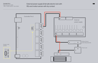
Wire the Kisi Controller Pro 2 to the external power supply
- Select one of the controller's four door relays. Note: The fifth (AUX) relay is for wiring intrusion detection hardware, such as sirens or third-party alarm systems.
- On the relay, identify the NO (Normally Open) and COM (Common) pins
- Wire the NO (Normally Open) pin of the controller to the IN (Input) wire of the external power supply
- Wire the COM (Common) pin of the controller to the GND (Ground) wire of the external power supply
- On the controller, set the jumper into the dry position
- Verify that all connections are secure and there are no loose wires
Wiring a REx (request-to-exit or push-to-exit) device and a motion sensor
- Wire the NC (Normally Closed) wire of the motion sensor to the COM (Common) wires of the external power supply
- Wire the COM (Common) wire of motion sensor to the COM (Common) wire of the REx (request-to-exit) device
- Wire the NC (Normally Closed) wire of REx (request-to-exit) device to the negative (-) wire of the magnetic lock
- Wire the NC (Normally Closed) wire of the external power supply to the positive (+) wire of the magnetic lock
- Verify that all connections are secure and there are no loose wires
Finalize the wiring
- Power the Kisi controller using the provided power supply and input. A blue light should come on if powered.
- Plug in the Ethernet cable. You should see a green blinking light on the top right-hand corner of the board. This indicates that the controller is online.
The Kisi Controller Pro 2 does not support alternating current (AC) wiring, so make sure the lock can work on direct current (DC). Also, the Kisi Controller Pro 2 only supplies up to 4 amperes total for the door locks that are drawing power from the circuit board. If you wish to power up more doors, do not exceed a total of 4 amperes for each Kisi Controller Pro 2.
Please refer to our list of recommended equipment for optimal door security.